The transmission controller is not receiving an acceptable signal from the circuit that reports input or turbine speed. That speed helps the controller calculate ratio and manage shifts, but the code does not identify which part of the sensor, wiring, target, or module path failed.
Joliet / Preserve the Data / Test the Circuit
P0715: Input/Turbine Speed Sensor Circuit - A Joliet Driver's Guide
P0715 guide for Joliet drivers: symptoms, tow decisions, input-speed data, circuit tests, repair scope, and proof the fault was resolved.
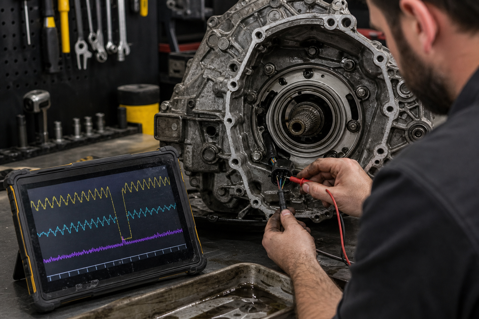
P0715 means the transmission controller detected an electrical or signal problem in the input or turbine speed sensor circuit. That signal helps the controller compare engine speed, converter or input-shaft speed, output speed, and commanded gear. When the signal disappears or becomes implausible, the vehicle may turn on a warning light, change shift strategy, raise line pressure, hold one gear, or limit performance.
P0715 does not name a failed sensor, prove that the transmission is slipping, or justify a rebuild by itself. The same code can result from a sensor, connector, external or internal harness, power or ground problem, damaged signal target, module or software issue, or a mechanical condition that makes the measured speed unreliable. The useful next step is to preserve the code details and prove which part of that chain failed on the exact vehicle.
01
What P0715 Can Feel Like From the Driver's Seat
A driver may notice a check-engine or transmission warning, a hard shift, delayed upshift, a transmission that stays in one gear, reduced acceleration, or engine speed that no longer matches the expected shift. Some vehicles use a high-pressure fail-safe strategy when speed data is missing, so the harshness can be a protective command rather than proof that a clutch pack suddenly failed. Other vehicles may show little more than a warning until the fault repeats.
Record the complete event instead of reducing it to 'it shifted badly.' Note the gear selected, road speed, engine speed, warning message, outside temperature, whether the vehicle was cold or fully warm, and whether cycling the key changed the behavior. A normal dashboard speedometer does not rule out P0715 because many vehicles calculate road speed from a separate output or wheel-speed signal.
02
Joliet Roads Can Help Define the Test Condition
The route where P0715 appears can separate an immediate electrical dropout from a heat- or vibration-sensitive fault. A warning that arrives during a cold start near downtown Joliet is a different test condition from one that appears only after stop-and-go traffic on Jefferson Street or Route 59. A fault during an I-55 or I-80 merge may need engine, input, and output speed recorded under controlled load rather than another short neighborhood drive.
Tell the diagnostic provider whether the vehicle had just crossed railroad tracks, hit a rough section of road, sat in summer traffic, or completed a longer run from Plainfield, Shorewood, Crest Hill, or Channahon. Also note passengers, cargo, trailer use, and any recent battery, starter, engine, or transmission work. These details do not diagnose the code, but they give the technician a realistic condition to reproduce without guessing.
03
When to Park the Vehicle and Ask About Towing
Stop driving and ask about an appropriate tow when the vehicle will not engage drive or reverse, repeatedly falls out of gear, slips severely, bangs into gear hard enough to affect control, overheats, loses fluid quickly, smells burnt, or cannot maintain speed safely. A fail-safe gear can leave limited acceleration for a merge or intersection, and continued clutch slip can create heat and debris that were not present when the electrical fault first appeared.
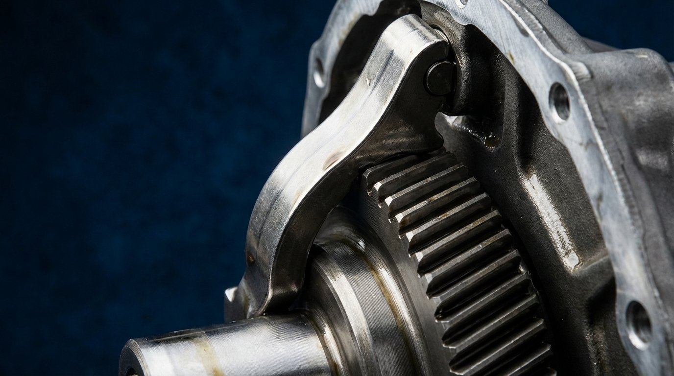
A stored P0715 code with normal engagement and stable shift behavior may allow a scheduled diagnostic visit, but the decision depends on the current symptoms, distance, traffic, weather, and ability to pull over. Do not use a cleared warning light as proof that the vehicle is safe. Clearing the code may also erase freeze-frame or event information that would have shown exactly when the signal failed.
04
Start With the Exact Code Record and Transmission ID
The first diagnostic step is a scan of every relevant module with a tool that can reach the transmission controller. Save confirmed, pending, history, and permanent codes; the failure subtype or suffix; freeze-frame or event data; transmission temperature; commanded gear; engine speed; input or turbine speed; and output speed. A generic reader that shows only P0715 may hide the manufacturer detail needed to distinguish an electrical fault from a range, plausibility, or intermittent signal fault.
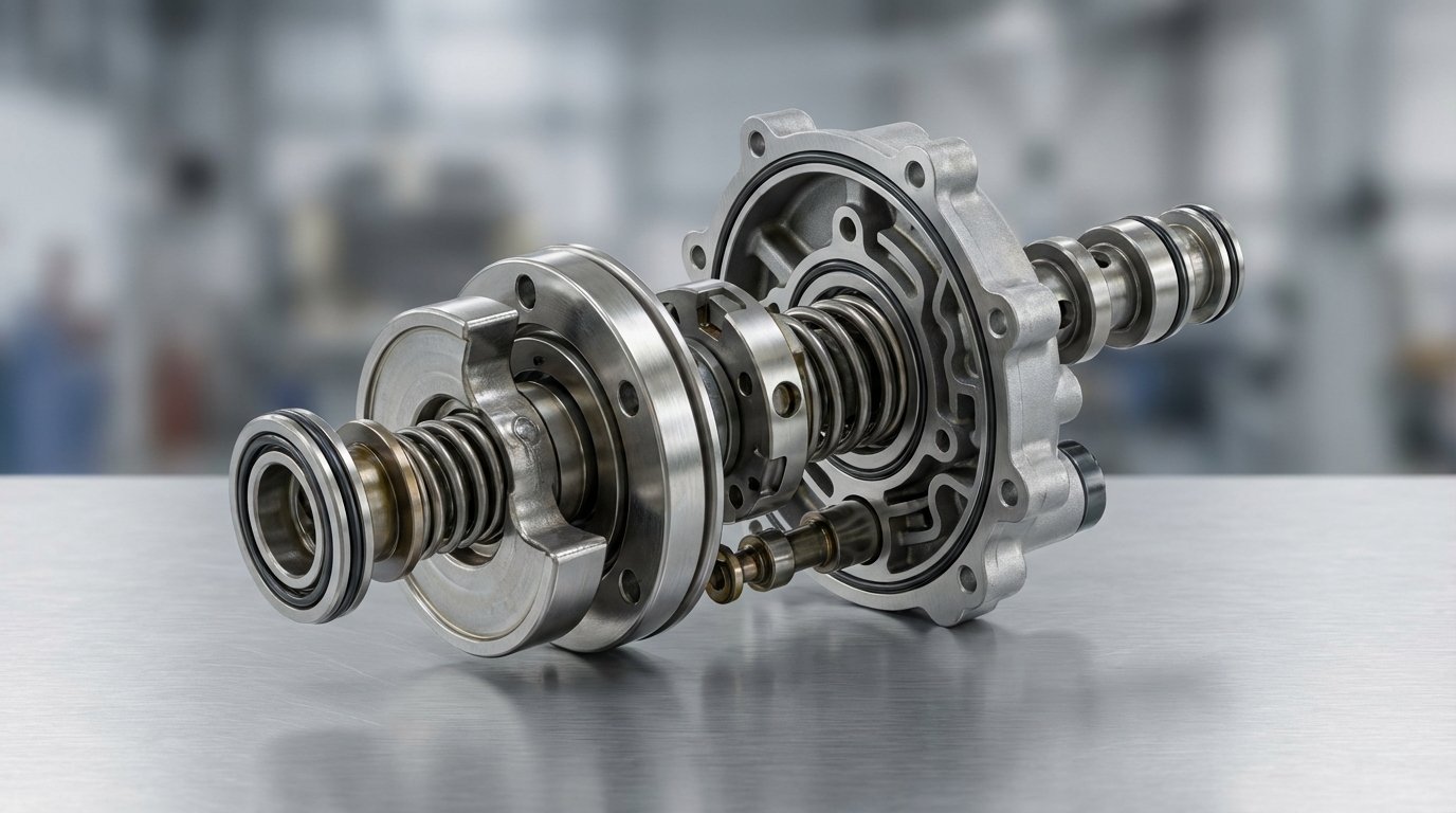
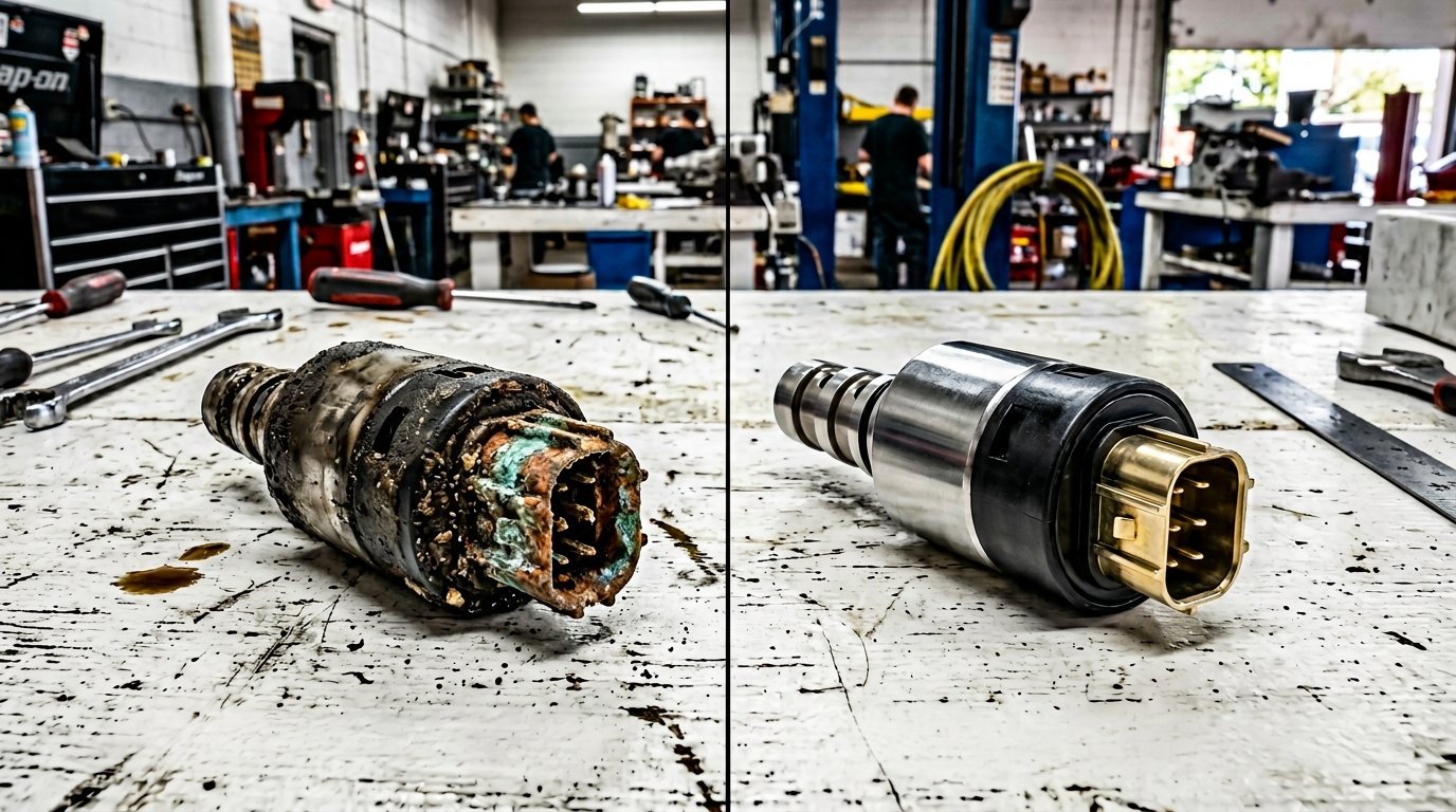
Next, identify the installed transmission by VIN, build data, engine, drivetrain, and case or calibration information. Sensor design and access vary widely. One unit may have an external two-wire magnetic sensor; another may use a powered Hall-effect sensor, internal harness, conductor plate, mechatronic assembly, or multiple input speed sensors. Testing the wrong circuit with a generic resistance or voltage number can create a false diagnosis.
| Code or record | What it adds | Why it matters |
|---|---|---|
| P0700 | The engine controller reports that the transmission controller requested the warning light | Read the transmission module; P0700 is not the root-cause code |
| P0715 | General input or turbine speed sensor circuit fault | Preserve subtype, status, and event data before naming a part |
| P0716 | Input or turbine speed signal range or performance concern | Compare the signal with engine and output speed under the same condition |
| P0717 | No input or turbine speed signal detected | Open circuit, power, ground, sensor, connector, or missing target signal moves higher on the list |
| P0718 | Intermittent input or turbine speed signal | Heat, vibration, terminal tension, harness movement, or an unstable target may be involved |
| P0720 | Output speed sensor circuit concern | A shared supply, ground, harness, module, or broader mechanical issue may affect ratio data |
| P0730-P0734 | Overall or individual gear-ratio disagreement | Validate both speed signals before treating a calculated ratio code as internal clutch failure |
05
Graph Engine, Input, and Output Speed Together
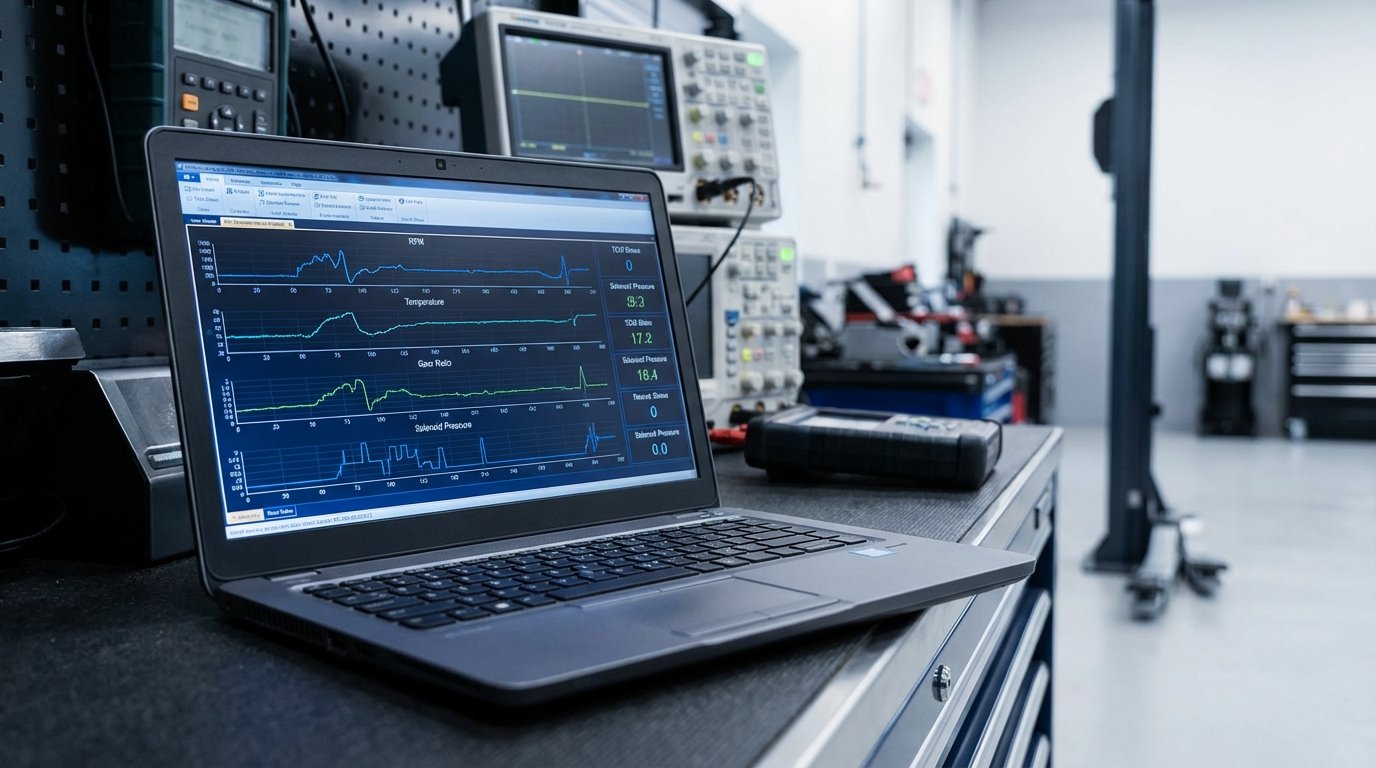
A useful road test graphs the signals together instead of watching one number. Engine speed, input or turbine speed, output speed, commanded gear, actual or calculated ratio, throttle, temperature, and converter-clutch command show whether the signal drops out before, during, or after the shift complaint. The test should reproduce the customer's event at the lightest safe load and stop if engagement or control becomes unreliable.
A flat zero input-speed value can indicate a dead circuit, but it can also result from scan-tool labeling, unsupported data, or a test condition in which that PID is not expected to move. A jagged value may point toward an intermittent connection or target problem, while a smooth but implausible value may require checking calibration, tooth count, sensor air gap, or internal speed relationships. Save the graph so the estimate can refer to evidence rather than memory.
| Data stream | Question to answer | Useful comparison |
|---|---|---|
| Engine RPM | Was engine speed stable or did it flare during the event? | Compare with turbine speed to understand converter or input behavior |
| Input or turbine RPM | Did the signal rise smoothly, drop to zero, spike, or freeze? | Compare with engine speed, output speed, and the commanded shift |
| Output RPM | Did road-side transmission speed remain plausible? | Separates one missing sensor signal from a broader ratio problem |
| Commanded gear and ratio | Which gear was requested when the fault appeared? | Shows whether the controller changed strategy after the dropout |
| Transmission temperature | Does the fault occur cold, warm, or only after heat soak? | Guides connector, sensor, fluid, and internal testing at the right condition |
| Battery and module voltage | Did system voltage fall or become unstable? | Prevents a low-voltage event from being mistaken for an isolated sensor failure |
06
Fluid Condition Is Evidence, Not a Shortcut Diagnosis
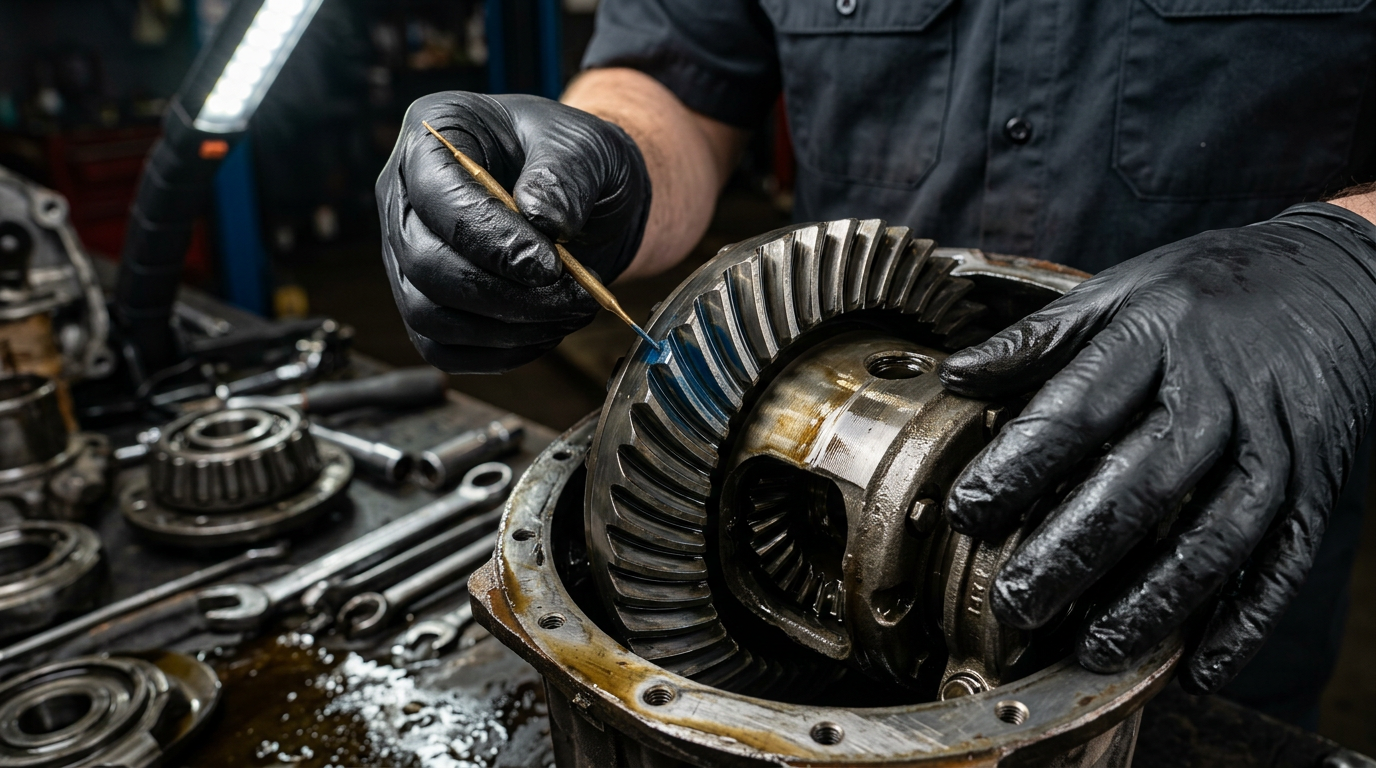
Check the fluid using the correct unit-specific temperature and level procedure. Record leaks, level, odor, color, and visible debris, but do not claim that dark fluid alone caused an electrical code. Low fluid, overheating, or heavy debris can accompany a mechanical problem that changes shaft speed, while metallic material can collect near some magnetic sensors or signal targets. Those findings must be connected to the actual signal failure.
A fluid exchange does not repair an open wire, loose terminal, failed sensor, damaged target, module input, or internal harness. Conversely, replacing a sensor will not correct clutch slip, bearing movement, or debris generation that made the signal implausible. If service is recommended, the written scope should state whether it is maintenance, part of access for a confirmed repair, or a response to documented contamination.
07
Test the Circuit Architecture the Manufacturer Actually Used
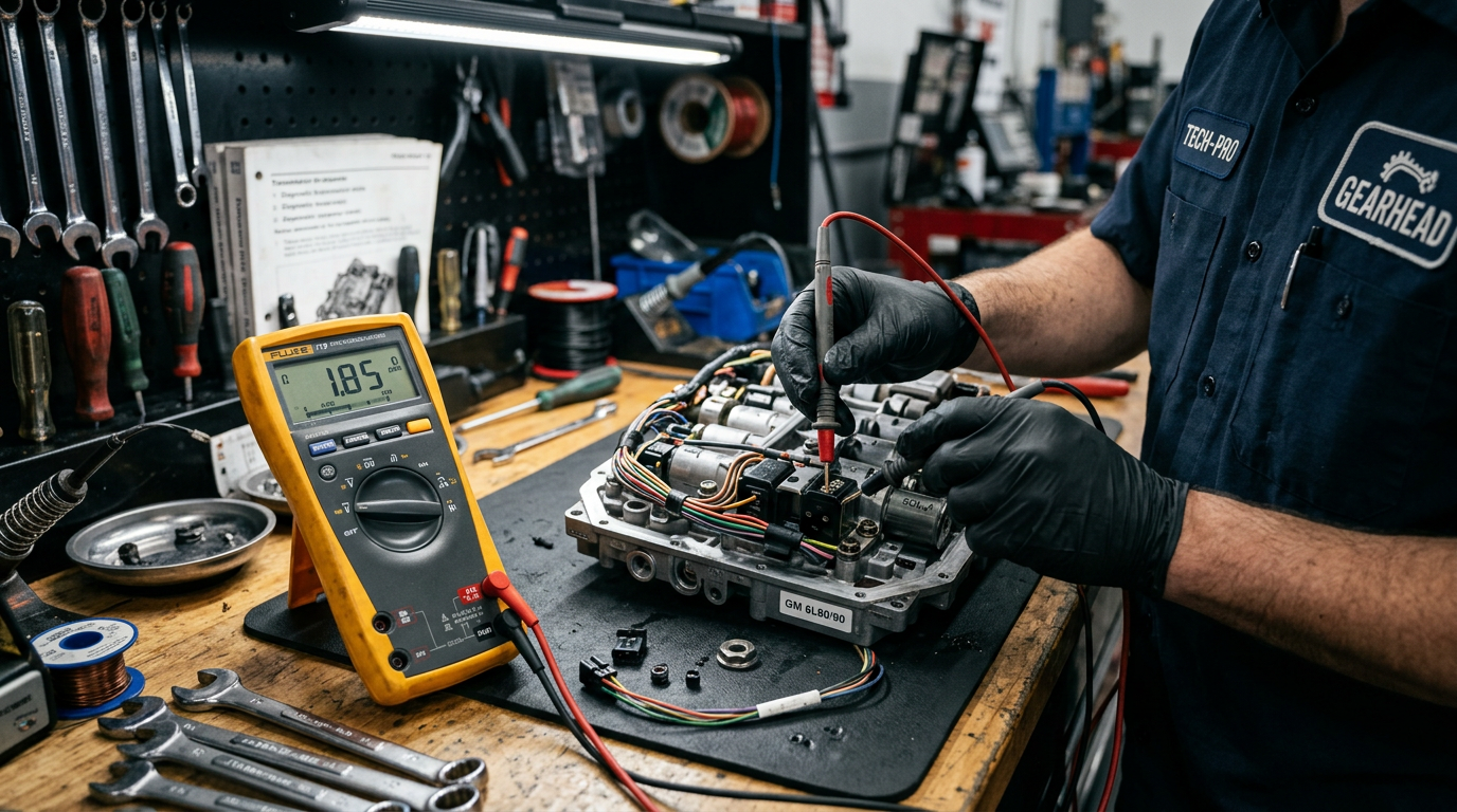
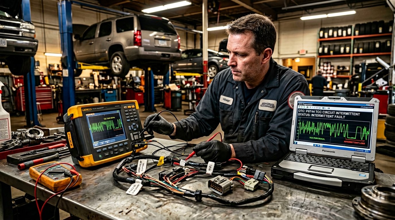
Circuit testing begins with the correct wiring diagram and service information. Depending on design, the test may include loaded power and ground checks, reference voltage, signal bias, continuity, resistance, terminal drag, harness movement, and waveform shape. A scope can reveal missing pulses or noise that a multimeter averages away. Never apply a generic voltage or resistance specification before confirming whether the sensor is passive, powered, internal, or shared with another circuit.
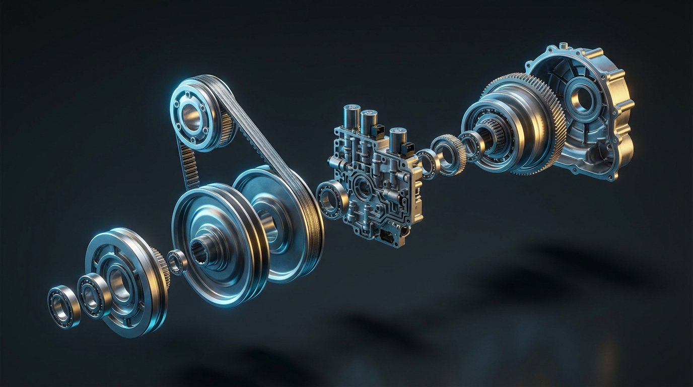
Manufacturer bulletins show why P0715 must remain vehicle-specific. Ford TSB 20-2393 addressed P0715 and related speed-sensor codes only on a defined group of 2020 Super Duty trucks with the 10R140 and a specific build-date limit. Jaguar Land Rover SSM73847 addressed P0715-64 with P0700-02 on defined 2017-2018 vehicles and distinguished a software adaptation path from a mechatronic fault. These are examples, not universal repair instructions; the VIN, code suffix, software level, and exact transmission control the procedure.
08
When the Evidence Moves Inside the Transmission
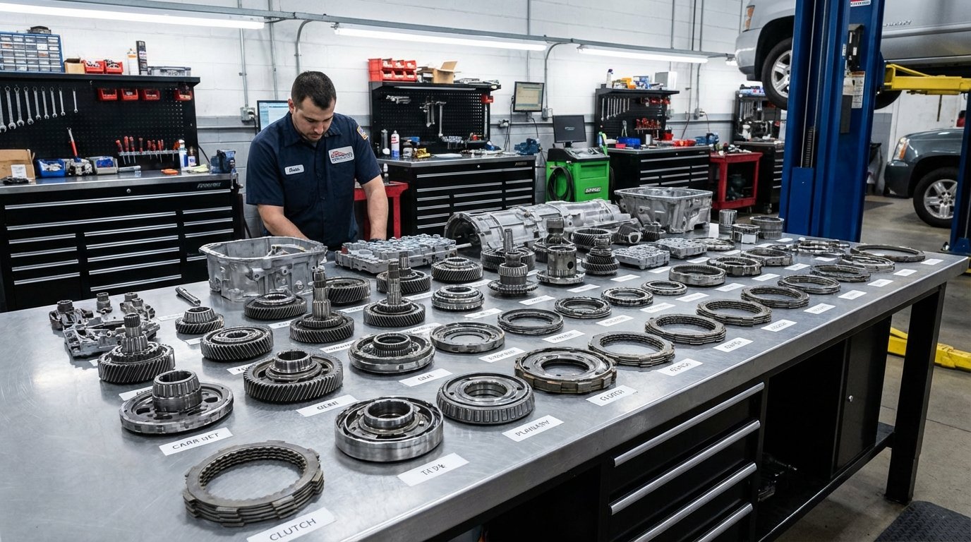
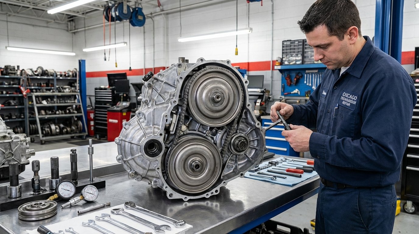
Internal inspection becomes reasonable when external power, ground, signal wiring, terminals, and module access test correctly but the sensor or signal target is inside the unit, or when the waveform shows a repeatable mechanical disturbance. Depending on design, access may require a pan, valve body, conductor plate, side cover, or transmission removal. The estimate should identify the access point and the evidence that justifies opening the unit.
Evidence for broader internal work is stronger when valid speed data confirms real ratio slip, the pan contains substantial friction material or metal, the input shaft or bearing has measurable movement, a reluctor or tone target is damaged, or a clutch element cannot hold under verified command and pressure. P0715 alone is not that evidence. A customer should be able to see how the findings progressed from circuit testing to internal diagnosis.
09
Match the Repair Scope to the Proven Failure
The smallest correct repair can range from terminal or harness work to an external sensor, internal harness, conductor plate, mechatronic assembly, software update, signal target repair, or internal transmission work. The estimate should name the failed path, list the access and fluid requirements, and explain whether programming, adaptation, or a relearn follows the repair.
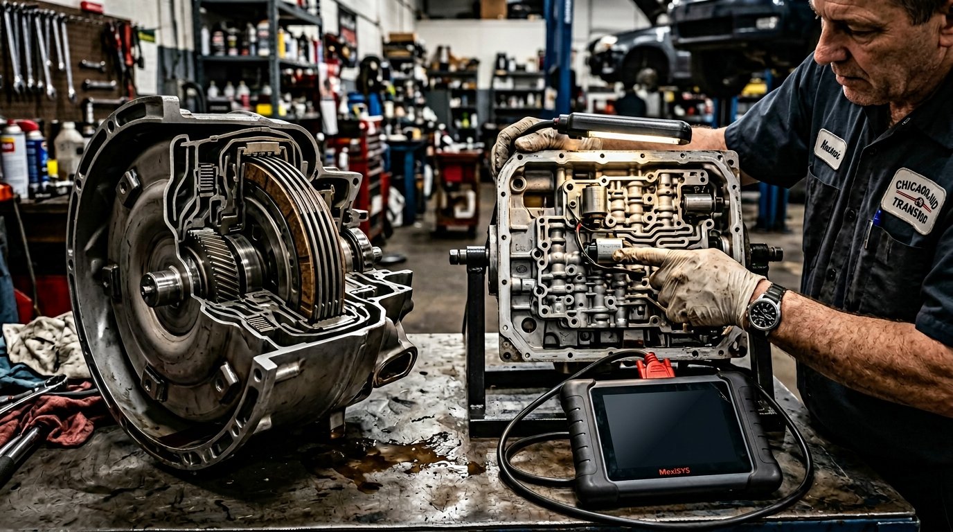
Avoid authorizing a sensor because its name appears in the code description. Ask for the failed test and the expected post-repair signal. If the recommendation changes after the pan or valve body is removed, the shop should pause at a defined approval point and document the new finding before expanding the work.
| Repair path | Evidence before approval | Scope questions |
|---|---|---|
| Connector or external harness | Voltage drop, poor terminal tension, corrosion, open, short, or waveform change during harness movement | Which wires or terminals, how is the repair sealed and supported, and how will the signal be retested? |
| External speed sensor | Correct power, ground, and harness path with a failed sensor output under the specified test | Is the sensor externally accessible, is fluid lost, and is an OEM relearn or drive cycle required? |
| Internal harness, plate, or mechatronic part | Fault isolated past the case connector or to an integrated sensor assembly | What must be removed, which seals and fluid are included, and is programming required? |
| Software, calibration, or adaptation | Exact VIN, code suffix, software level, and manufacturer procedure match | What update or adaptation is performed and what operating test confirms it? |
| Signal target or internal mechanical repair | Damaged target, bearing movement, debris, or validated ratio and clutch failure | Is focused internal repair practical, or does teardown support rebuild or replacement? |
10
A Rebuild Requires More Than a Speed-Sensor Code
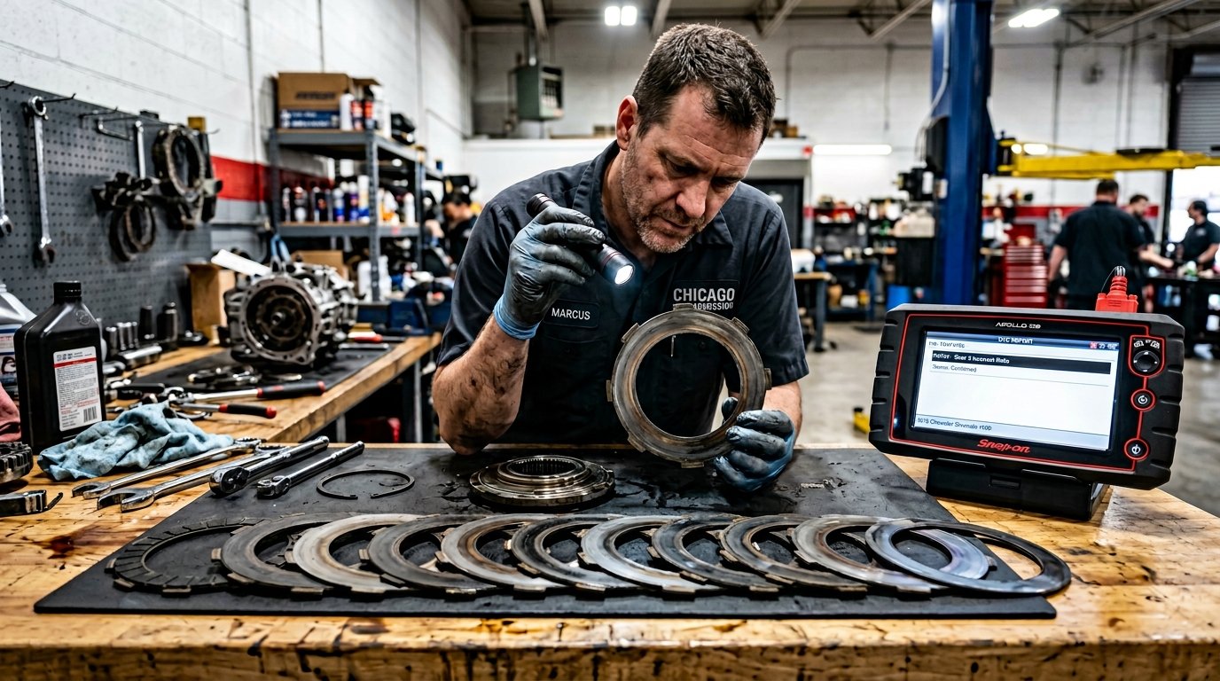
A rebuild belongs in the conversation only when testing shows internal wear or damage beyond the serviceable sensor circuit. Examples include clutch material and metal in the pan, a damaged target caused by shaft or bearing movement, verified clutch slip with valid speed signals, pressure loss tied to internal leakage, or hard-part damage found during authorized teardown. The findings should identify the failed function, not simply the code.
If rebuilding is proposed, compare the converter, pump, valve body, friction elements, seals, bushings, bearings, hard-part allowance, cooler procedure, programming, fluid, tax, and post-repair testing on the same written scope. Ask which items are included, which findings could change the price after teardown, and when another authorization would be required.
11
Replacement Is a Vehicle Decision, Not a Code Response
A used or remanufactured transmission may be considered when the original unit has extensive internal damage, required hard parts are unavailable, or the installed total and downtime compare favorably with rebuilding. P0715 by itself does not support replacement. Confirm the exact unit, interchange, calibration, drive configuration, included converter or related parts, cooler requirements, core charges, freight, and programming responsibility.
A used unit can carry the same age, sensor, harness, or internal wear risk as the original. A remanufactured unit can offer a clearer assembly scope, but the installer still needs to correct external wiring, cooling, voltage, or control problems that caused or accompanied the original fault. Compare the installed plan and verification process, not only the price of the transmission itself.
12
Put Every P0715 Estimate on the Same Sheet
A useful estimate separates the confirmed work from contingent work. It should state the diagnostic result, repair path, access labor, parts source, fluid, seals, programming, taxes, towing, and post-repair test. If the diagnosis requires internal access, the document should explain what the initial authorization covers and which findings would trigger another approval.
Keep the original code report, freeze-frame, graphs, waveform captures, photos, and final invoice. These records help compare two recommendations and prevent duplicate testing. They also make it easier to determine whether a returning warning is the same circuit fault, a companion code, or a new transmission behavior.
| Estimate line | What should be written | Decision protected |
|---|---|---|
| Diagnostic evidence | Code status and suffix, module data, reproduced condition, circuit or waveform result, and related findings | Prevents a code description from becoming a parts order |
| Confirmed repair | Exact sensor, connector, wire, internal assembly, software step, target, or mechanical work | Defines what is known before work begins |
| Access and labor | External access, pan removal, valve-body access, side-cover work, or transmission removal | Explains why the same named part can have different installed totals |
| Fluid, seals, and hardware | Specification, quantity, pan gasket, one-time hardware, connector seals, and disposal | Avoids incomplete sensor or internal-access quotes |
| Programming and relearn | Software update, module setup, adaptations, resets, and required drive cycle | Clarifies electronic completion work |
| Contingent findings | What could be discovered after access and the approval point before cost increases | Limits open-ended authorization |
| Verification | Signal graph, code recheck, shift test, fluid level, leak check, and customer complaint confirmation | Defines how the repair will be proven |
| Installed total | Parts, labor, programming, fluid, taxes, towing, freight, and core charges where applicable | Makes competing options comparable |
13
Balance Repair Depth With Downtime and Vehicle Condition
A confirmed external circuit repair is a different ownership decision from internal access or a complete transmission. Consider vehicle condition, rust, mileage, engine and cooling system health, other warning lights, current loan balance, daily transportation needs, and how long the vehicle is expected to stay in service. Do not let age alone turn a repairable wiring fault into a replacement recommendation.
Downtime matters for a Joliet commuter, family vehicle, delivery van, or work truck. Ask whether the vehicle must remain during diagnosis, whether parts are VIN-specific, and whether programming or a drive cycle affects completion. A clear diagnostic record can reduce repeated appointments and help the owner choose between a focused repair, authorized internal inspection, rebuild, replacement, or retiring the vehicle.

14
Prove the Signal and Shift Strategy After the Repair
Post-repair verification should repeat the condition that set P0715 whenever it is safe to do so. Confirm stable module communication, correct voltage, a clean input-speed signal, plausible engine-input-output relationships, expected gear commands, and no returning confirmed or pending code. If the repair involved software or adaptations, record what was updated or reset and what may continue learning.
Also verify the correct fluid level at the specified temperature, no leaks at disturbed seals or connectors, and the original shift or fail-safe complaint. The final invoice should name the repaired circuit or component and summarize the verification. 'Code cleared' is not enough because any scan tool can erase a code without correcting the condition that caused it.
15
What to Send Before a P0715 Diagnostic Visit
Send the year, make, model, mileage, engine, drivetrain if known, complete code printout, warning messages, service history, battery or repair history, and a plain description of the event. Include whether the vehicle was cold or hot, which range was selected, whether engine speed flared, whether every gear still worked, and the Joliet-area route where the fault appeared.
If engagement is unreliable, slip is severe, the vehicle is stuck in a fail-safe gear, fluid is leaving quickly, or the vehicle cannot accelerate safely, ask about towing before moving it. If it remains stable, arrange testing before clearing data or approving a sensor, valve body, rebuild, or replacement. The immediate goal is to preserve evidence and turn one code into a specific, written decision.
Questions Before Major Work
No. Replacement is appropriate only after the exact sensor architecture, power, ground, signal, wiring, connector, and operating data isolate the fault to the sensor or integrated assembly. Some vehicles use internal sensors or manufacturer-specific software and mechatronic strategies.
The code alone cannot decide that. Park the vehicle and ask about towing if it will not engage, slips badly, loses a gear, overheats, leaks heavily, shifts violently, or cannot maintain speed safely. Mild behavior still deserves prompt diagnosis before the data is cleared.
P0715 is a general circuit fault, P0716 describes a range or performance problem, and P0717 indicates no signal. The exact manufacturer definition and suffix still matter, and all three require testing on the installed transmission.
Fluid condition can be relevant when low level, heat, metal, debris, or mechanical wear affects the sensor environment or shaft behavior. Dark fluid alone does not prove the cause, and a fluid exchange cannot repair an open circuit, failed sensor, damaged target, or module problem.
No. A rebuild requires separate evidence of internal wear or damage, such as validated clutch slip, pressure loss, substantial debris, bearing or shaft movement, or damaged hard parts. A connector, harness, sensor, integrated plate, or software repair may be enough when testing proves that path.
Sensor location and design vary. Some are external; others are inside the pan, valve body, conductor plate, mechatronic unit, or deeper in the transmission. Compare diagnosis, access, parts, fluid, seals, programming, contingent findings, and verification on the same installed scope.
Turn P0715 into a tested, written repair path.
Send the vehicle details, complete code report, warning messages, exact shift behavior, and where the fault appeared around Joliet. Use that evidence to decide between towing, circuit testing, a focused repair, internal inspection, rebuild, or replacement.